Documenting a Software Architecture
It’s clear that documenting architectures is one of the most boring important tasks of Software Engineering.
A two-sided activity
There are many good reasons why we have to document our software projects:
- Other members can understand and evaluate the design of this software.
- We can understand what we implemented when we return to it after a certain of time.
- We can do analysis on the design to evaluate the performance of this system, prevent errors occur before we start the implementation phase.
Documenting architectures also have some downsides, like:
- The documents will gradually out of date with the code. Keeping the architecture documents
current is often an overlooked activity, especially under the pressures in a project. - Documenting is time consuming and expensive.
So when should we document software architectures?
There are a lot of factors to consider if we need to document or not. Projects with little prospect of a long life probably don’t need a lot of documentation. The other factor to consider when documenting is the needs of project stakeholders, including the various roles like developers, testers, managers, etc. In a small team, the documentation can be minimal and can be replaced by interpersonal communication, it saves our time. In a large team, however, the documentation becomes more important for describing the system, especially companies that work in multiple countries and in many offices. Therefore, it is important to think carefully before documentation because it takes time to develop and maintain along with projects.
In this post, I will introduce you to the most popular language to document software architectures: Unified Modeling Language.
Unified Modeling Language (UML)
UML is a modeling language of Software Engineering. It provides a standard way to visualize the design of a system or an application. UML includes both structural and behavioral diagrams for representing a software system:
- A structual diagram describes static architectures of its system.
- A behavioral diagram shows the interactions between entities inside a system.
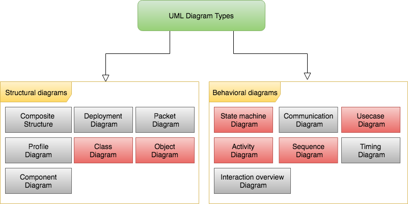
Note that I have never used Component diagrams, Package diagram, Deployment diagrams, Profile Diagram, Composite Structure diagrams, Communication diagrams, Interaction Overview diagrams and Timing diagrams so I’m going to skip these diagrams in this post.
Structual diagrams
Class diagrams
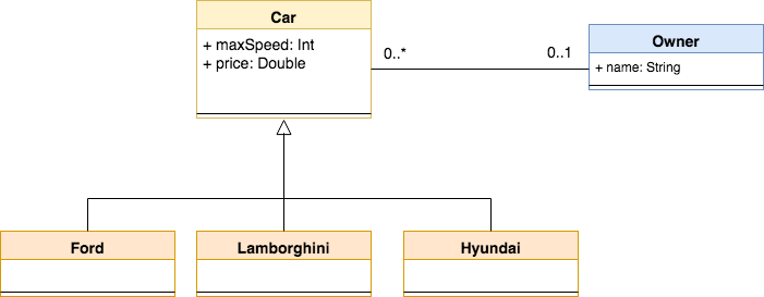
A class diagram describes the structure of a system by showing relationships between its classes. It also shows attributes and methods of each class. The main purpose of class diagrams is to get the general overview of the system.
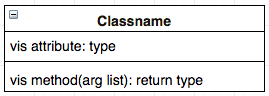
Where vis = visibility
| Syntax | Visibility type | |
|---|---|---|
| + | Public | If a variable or a method is static, it has to be underlined. |
| # | Protected | |
| - | Private | |
| ~ | Package |
The following lines introduce some major replationships in Class diagrams.
| Mark | Meaning |
|---|---|
| Implementation | Class B implement the behaviors that are defined in Class A. 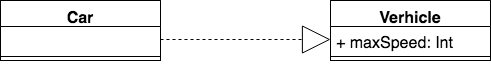 |
| Inheritance | Class B has IS-A relationship with class A, or we can say Class B is a type of Class A. 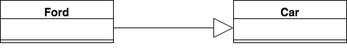 |
| Dependency | It exists between two elements if changes to the definition of one element may cause changes to the other. 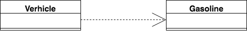 |
| Association | A binary association (with two ends) is normally represented as a line. It indicates that Class A contains one or more properties belonged to class B, or vice versa. 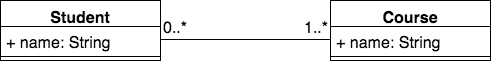 |
| Aggregation | It is a special case of Association. We can say Class A is aggregated with Class B if Object X as an instance of class A is destroyed but Object Y as an instance of class B is still exist. 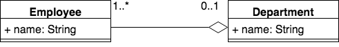 Here, the lives of both Employee and Department are independent of each other. Employees may exist without a department. |
| Composition | It is a special case of Aggregation but it is stronger than Aggregation relationship. If Object X as an instance of class A is destroyed, the Object Y as an instance of class B will also be destroyed. We also say Composition is HAS-A relationship.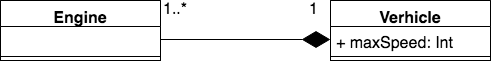 Here, If we delete the verhicle object then all the engines are automatically deleted. The engines do not have their independent life cycle, it depends on the verhicle object’s life. |
Instance diagrams (Object diagrams)
Basically, an instance diagram is similar to the class diagram which it depends upon. However, an instance diagram is just a snapshot of the system at some point in time, and it shows what values those objects contain at this specified time. Instance diagrams are often used to make prototypes of a system, and to get more understand the system in a practical view.
Symbols and notations of instance diagrams can be utilized in class diagrams.
Example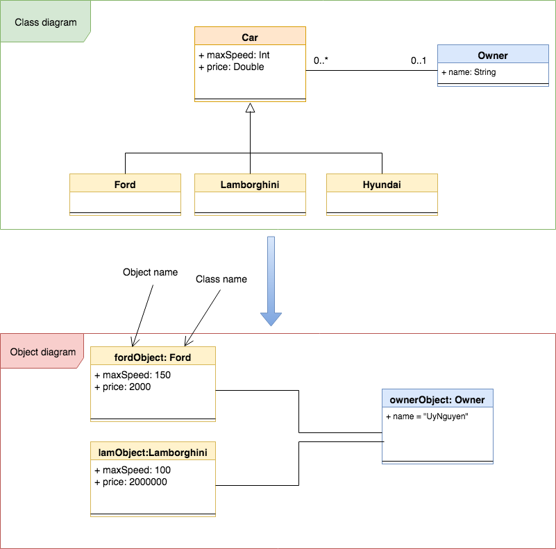
Behavioral diagrams
Activity diagrams
An activity diagram shows the flow from one activity to another activity (An activity is a function performed by the system). Note that messages are not included in activity diagrams.
An activity diagram is often used to describe the high level of the system, mainly for business users or non-technical persons. It can also describe the steps in a use case diagram.
Basic symbols and components: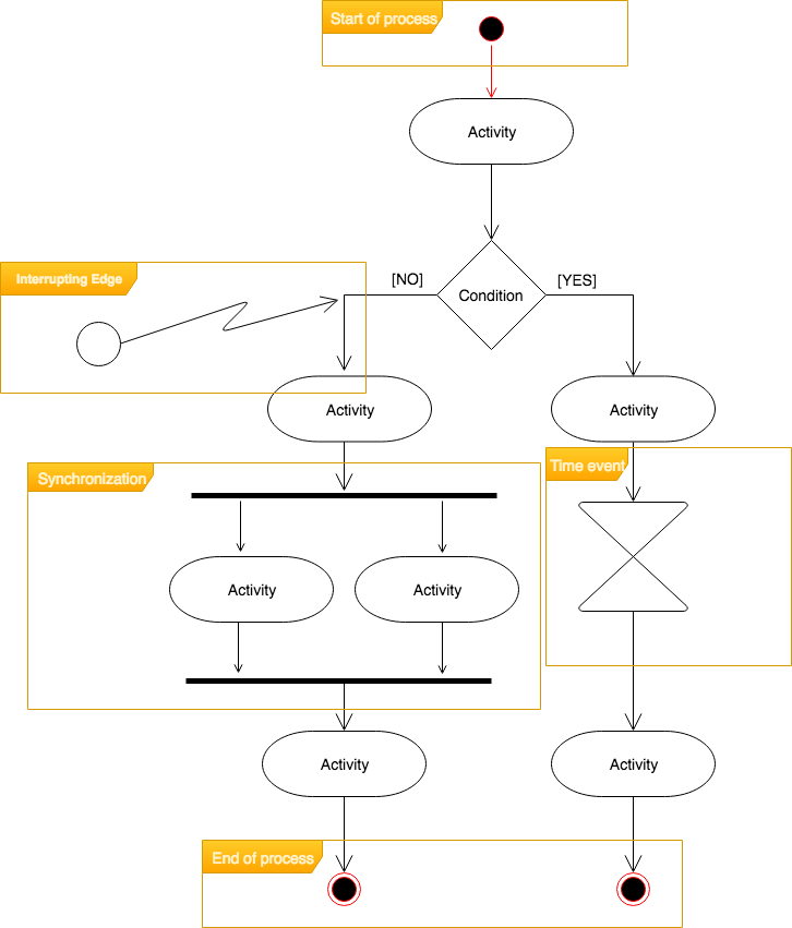
| Basic Symbol | Meaning |
|---|---|
| Start point | It represents the initial action state. |
| Activity | It represents an activity of the process. |
| Condition | Use this symbol when an activity requires a decision prior to moving on to the next activity |
| Synchronization | It indicates that multiple acitivies are performed synchronously. |
| Time event | This refers to an event that stops the flow for a time. |
| Interrupting Edge | An event that interrupts the flow. |
| End Point | It represents the final action state. |
Sequence diagrams
A sequence diagram shows how objects and components interact with each other to complete a function.
Basic symbols and components: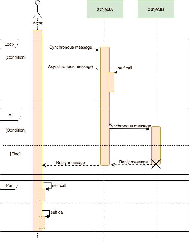
| Basic Symbol | Meaning |
|---|---|
| Actor | It shows entities that interact with the system. |
| Object | It represents an object in UML. |
| Activation box | It represents the time needed to complete a task. |
| Loop | It indicates loop statements. |
| Alternative | It indicates condition statements. |
| Parallel | Each task in the frame represents a thread of execution done in parallel. |
| Synchronous message | The sender must wait for a response to a message before it continues. The diagram should show both the call and the reply. |
| Asynchronous message | The sender does not need to wait for a response to a message before it continues. |
| Return message | Messages are replied to calls. |
| Delete object | It indicates that the object will be detroyed. |
State Machine diagrams
The main purpose of state machine diagrams is to show the state changing of an object during its lifetime.
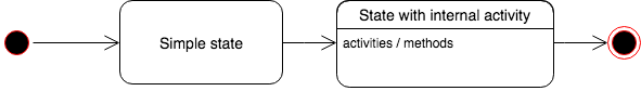
| Basic Symbol | Meaning |
|---|---|
| State | A state represents a situation during the life of an object. |
| Initial State | The object’s initial state. |
| Final State | The object’s final state. |
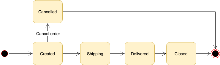
The following example shows the transition state of an order.
Use Case diagrams
An use-case diagram shows how the users or other external applications interact with the system. It also shows the scope of the system.
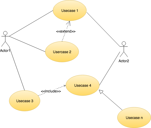
| Basic Symbol | Meaning |
|---|---|
| Actors | They represent the users or external systems that interact with our system. |
| Use cases | They represent the different uses that a user might have. |
| Associations | There are two types of associations: Actor-use case and use case - use case. an Actor - use case association indicates which actors are associated with which use cases. An Use case - Use case association shows the relationship of two use cases: - Include: A use case “include” another if it is a required action by the use case. - Extend: A use case “extend” another if it is an optional use of the use case. - Generalization: The use case inherits the structure, behavior, and relationships of another. 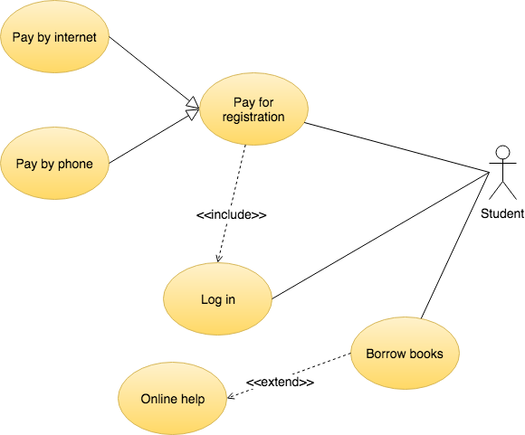 |
Have you ever heard about Business Process Model and Notation (or BPMN)?
“Business Process Model and Notation (BPMN) is a standard for business process modeling that provides a graphical notation for specifying business processes in a Business Process Diagram (BPD).” (Wiki).
The main objectives of BPMN are:
- To provide a set of standard notation that is understandable by business stakeholders.
- Often used to defined business logic because it has more complete concepts of events and it supports asynchronous message exchanges, which are important in business processing. BPMN is similar to activity diagram from UML.
An Example of BPMN.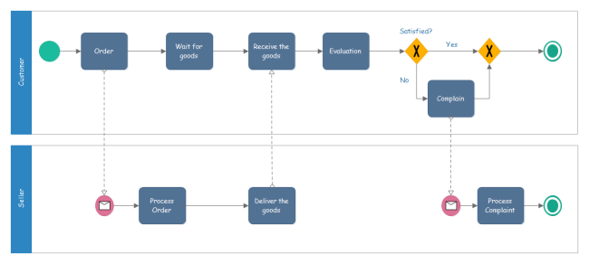
Conclusion
In this post, I showed you the general ideas of some popular UML diagrams, and showed you the main difference between the UML and the BPMN. Of course, there’re still a lot of purposes and notations of those diagrams that I can not list out here because of the scope of this post.
If you are interested in UML, you can download the full document of UML here (The latest version of UML is 2.5.1).
Thanks for reading.
References
[1] Essential Software Architecture (2011, Springer-Verlag Berlin Heidelberg)Ian Gorton (auth.), Chapter 8 Documenting a Software Architecture.